
Hardware Installation
DO NOT CONTINUE WITH THE HARDWARE INSTALLATION OF THE EYEDRO ELECTRICITY MONITORING SYSTEM UNTIL YOU HAVE READ THE IMPORTANT SAFETY INFORMATION SECTION OF THIS GUIDE
Materials You Will Need
- Eyedro Electricity Monitor box contents
- Approved bushing or connector (not included)
- Labels (optional – not included)
- Two (2) #8 (4.2mm) pan head, round head or button head mounting screws (optional – not included)
- Tie wraps (optional – not included)
Tools You Will Need
- Screwdriver
- Flashlight
- Pliers
Locate the Service Panel
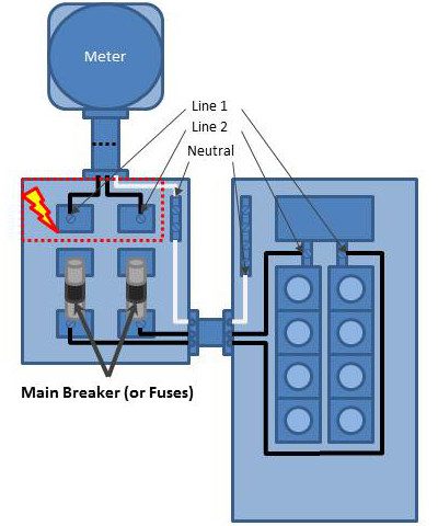
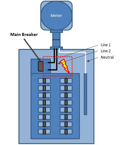
Locating the electrical service panel is the first step in hardware installation. The electricity panel is typically located in the garage or utility room of the building – although this is not always the case. The below diagrams show two typical 120/240V single (split) phase electrical service configurations:
PRO TIP: A quick way to find the electrical panel is to locate the electricity meter. These are often on the outside of the building. The electrical panel is typically on the wall directly behind it inside the building.
Service Box and Distribution Panel
In some cases, the service entrance wires, from the utility company, feed into a box that is isolated from the distribution panel.
In this configuration, current sensors can be installed on the Line wires in either the service entrance panel or distribution panel.
Combination Service/Distribution Panel
In some cases, the service entrance wires, from the utility company, and main breaker are integrated into a single main electrical panel.
In this configuration, current sensors are installed on the Line wires between the main breaker and the meter.
Install Current Sensors
Current sensors are installed on the individual line (live/hot) wires only. This must be done inside the electrical panel or junction box where the electrical connection is separated into the individual line, neutral and ground wires.
- Do not install sensors on neutral or ground wires.
- Do not install sensors on extension cords, appliance cords or sheathed cables.
- Do not install sensors on wires exceeding the max rating of the sensor.
CAUTION: Even with the main breaker in the ‘OFF’ position, the service entrance wires will still be electrified (before the breaker). Extreme caution should always be taken while working around electricity during hardware installation.
- Turn off the power by disengaging the main disconnect switch or turning off the main breaker.
- Carefully remove panel cover(s) to expose service entrance wires.
- Carefully remove a ‘knockout’ on the side of the panel and add an approved bushing or connector to protect the wires that will pass through it.
- Install one current sensor over each service entrance line wire.
- Squeeze the clamp to open the sensor.
- Carefully place the wire in the sensor opening.
- Carefully close the sensor by releasing the clamp. Ensure the sensor is completely closed.
- Optionally, use tape or other label to uniquely identify each sensor at the end of the wire nearest the connector (i.e., “Sensor 1”, “Phase A”, etc.).
- Route sensor cables through the bushing/connector so the plug ends are on the exterior of the panel.
- Once all sensors are installed correctly, replace panel cover(s).
- Turn on the power.

Alternate Applications
The most common application of Eyedro Electricity Monitoring products is for monitoring of the electrical service entrance of a building. However, there are other common applications where Eyedro Electricity Monitoring products are often used. The following sub-sections provide a brief overview of some of the most common applications.
To use Eyedro Electricity Monitoring products in one of these applications, follow ALL instructions and precautions from the Service Entrance installation procedure but substitute step 4 to install the sensors on the line/live conductor of your desired circuit.
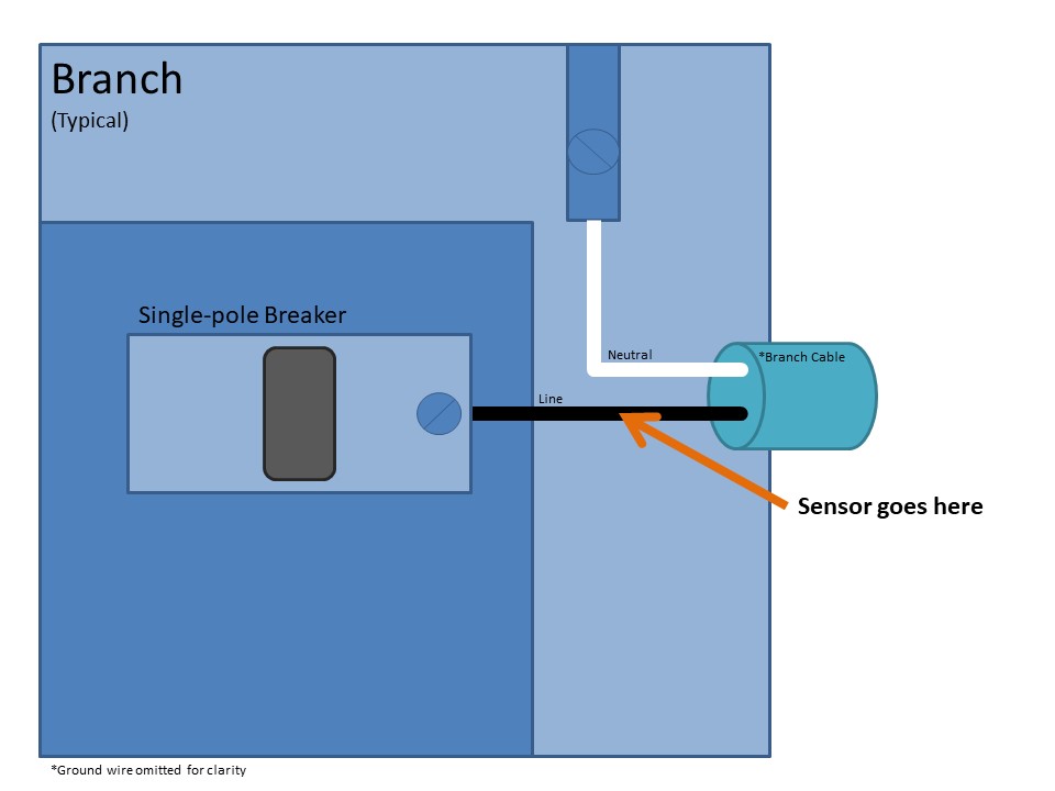
Branch circuit monitoring
Branch circuits are typically used for lighting and receptacles throughout the building. These circuits can be identified by a single-pole breaker in the electrical panel. Cabling typically consists of black (line) and white (neutral) conductors with a bare copper (or green) ground conductor.
One (1) sensor is required for monitoring branch circuits. The sensor should be installed on the line wire of the circuit (typically black).
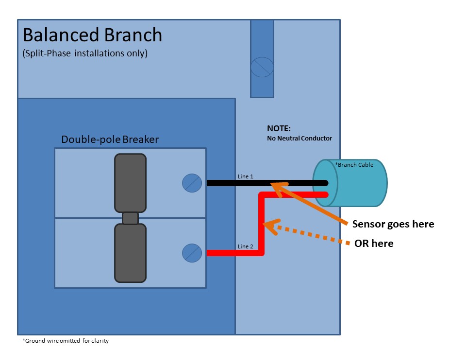
Balanced Branch Circuit Monitoring
Balanced branch circuits are common in split-phase electrical services and typically used for large appliances throughout the building. Common examples of balanced loads are electric heaters/baseboards, electric water heaters, air conditioners, heat pumps, pool pumps, etc. These circuits can be identified by a double-pole breaker in the electrical panel. Cabling typically consists of black (line 1) and red (line 2) conductors with a bare copper (or green) ground conductor. Note: these circuits do not have white (neutral) conductors.
One (1) sensor is required for monitoring balanced branch circuits. The sensor should be installed on either line wire of the circuit (typically black or red).
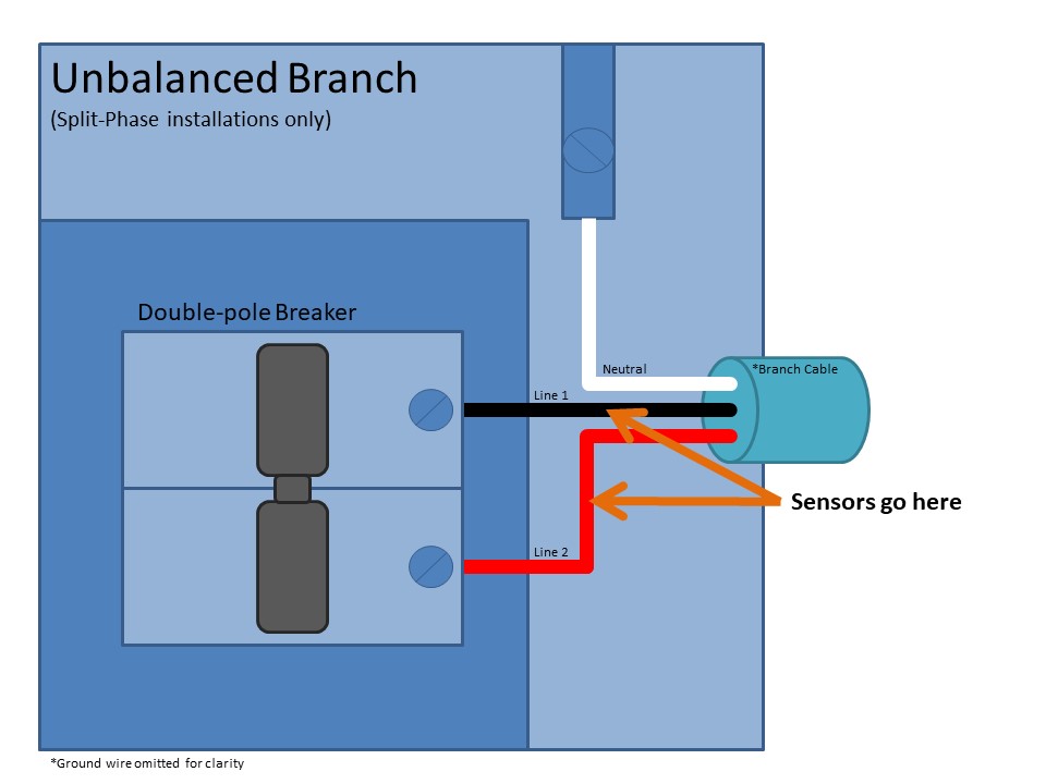
Unbalanced Branch Circuit Monitoring
Unbalanced branch circuits are common in split-phase electrical services and typically used for large appliances, split receptacles, and sub-panel feeders throughout the building. A typical split-phase residential service entrance is also an example of a 240V unbalanced circuit. These are circuits with both 120V and 240V components. Common examples of 240V unbalanced loads are stoves, electric dryers, kitchen receptacles, sub-panels, etc. These circuits can be identified by a double-pole breaker in the electrical panel. Cabling typically consists of black (line 1), red (line 2), and white (neutral) conductors with a bare copper (or green) ground conductor.
Two (2) sensors are required for monitoring unbalanced circuits. The sensors should be installed on both line wires of the circuit (typically black and red).
Three-Phase Monitoring (Delta or Wye)
Three-phase installations are common in commercial and industrial environments. These installations require the use of Eyedro Business (ExB*) products. Details and installation instructions for these products are outside the scope of this document.
Mount Eyedro Device
Vertical (wall) Mounting
- Write down the 8-digit serial number from the back of the module. This will be required during software setup.
- The serial number will be in the format “123 – 45678“
- Find a clear area on the wall beside the electrical panel.
- Make sure all cables will easily reach the module before securing.
- Equipment shall not be mounted within 50.8 mm (2 in) in of any live parts including primary conductors, primary terminals, primary lugs. This requirement excludes insulated cables.
- Equipment attached to the enclosure shall not contact the panel interior insulation.
- Mounting provisions shall not be attached to any live part.
- Do not install equipment in any area where breaker arc venting exhaust gasses could be re-directed as a result of equipment installation.
- Secure the module using either:
- Screws (recommended method)
- Drive the two (2) pan head screws into the wall surface through the flange holes on the sides of the enclosure.
- Carefully tighten the screws until snug. Do not overtighten or it may cause damage to the flange(s).
- Ensure secure fit.
- Double-sided tape
- Cut several pieces of double-sided tape and place on back of module.
- Peel tape backing off.
- Press module carefully but firmly against surface to be mounted on.
- Hold in place as per tape instructions.
- Ensure module is held securely in place.
- Screws (recommended method)
Horizontal (surface) Mounting
Mounting is not required for horizontal installations (i.e., on a desktop or shelf). If added security is desired, follow instructions for vertical mounting using screws or double-sided tape.
Connect Cabling
Important
- Ensure all connectors and sockets are free from damage prior to mating them.
- Ensure the retention clip on the Ethernet cable is intact.
- Never force connectors or apply levering action.
- Ensure all connections are secure.
Ethernet Installations
- Connect sensor cables to the Eyedro module.
- Connect one end of Ethernet cable to Eyedro module.
- Connect the other end of the Ethernet cable to the router (or Internet access point).
- Connect the appropriate end of the low-voltage power adapter to the Eyedro module.
- Monitoring devices use a power supply with a 6V AC output.
- Plug the other end of the low-voltage power adapter into a nearby AC wall receptacle.
- Devices should not be plugged into a UPS (Uninterruptible Power Supply) as they may result in inaccurate/incorrect measurements.
- Optionally, secure all wiring neatly with tie wraps (not included).
Wi-Fi Installations
- Connect sensor cables to the Eyedro module.
- Connect the appropriate end of the low-voltage power adapter to the Eyedro module.
- Monitoring devices use a power supply with a 6V AC output.
- Plug the other end of the low-voltage power adapter into a nearby AC wall receptacle.
- Devices should not be plugged into a UPS (Uninterruptible Power Supply) as they may result in inaccurate/incorrect measurements.
- Optionally, secure all wiring neatly with tie wraps (not included).