Device Setup Wizard
The Device Setup Wizard plugin allows you to configure the device and verify it is operating correctly. This tool is intended to be used in the event that you are installing the Eyedro Metering product(s) for another user (i.e. you are not the end user), to configure the device and verify it is operating correctly before leaving job site.
NOTE: If you are the end user, it is recommended to use the Device Configuration plugin within the MyEyedro Cloud service.

- Wizard Panel. The region of the plugin that houses all controls and settings for the current step in the device setup wizard.
- Wizard Navigation buttons. Progress through the steps of the device setup wizard
- Cancel (x)- Abort the device setup at any time without completing the setup and verification. NOTE: Any settings changed, up to the point of canceling, WILL NOT be reverted.
- Previous (<<)- Navigate to the previous step in the wizard.
- Next (>>) – Navigate to the next step in the wizard.
- Finish ()- Exit the wizard.
- Device Verification panel.
Device Setup Wizard Tools and Options

- Plugin Tools:
- Options. Expand or collapse the options menu.
- Check Show Verify Panel option to always have the verify panel visible during setup. With this option unchecked, the verify panel will be displayed as an additional (final) step in the wizard.
- Check Show Advanced Settings option to display all advanced device settings.
- Electricity monitoring devices only – Check Show Extended Sensor Types option to display a complete list of all available sensor types. By default this option is unchecked resulting a shorter list of the most common electricity sensor types.
- NOTE: If you do not see the sensor you are trying to install, ensure this option is checked.
- Electricity monitoring devices only – Check Show Split-Phase Topology option to display single phase topology diagrams using a split-phase image (most common in North America).
- Check Skip Device Unclaim option to not un-claim the device after the wizard is complete. By default this is unchecked to ensure the device is unclaimed and ready for the end-user to add it to their MyEyedro user account. If you are an installer (and not the end-user), this option should be left unchecked.
Device Setup Wizard Steps
The setup wizard will walk you through configuring and testing your hardware after successfully adding it to your account.
Connect to Device (Common)

- Enter the Serial Number. The serial number is located on a label on the physical hardware.
- Click ‘Connect‘. Upon success, you will see State and Last Comm(unication) fields indicating the device is communicating with the Internet.
- IMPORTANT: The device must be powered on and connected to the Internet.
- If the device is not actively communicating with the Internet, you will be presented with buttons to aid in troubleshooting the connectivity. Click on the appropriate; Troubleshoot Wi-Fi Connectivity or Troubleshoot Ethernet Connectivity button and proceed through the troubleshooting steps provided.
- Additional troubleshooting steps can be found here.
- Click ‘Next (>>)’ to proceed to the next step in the wizard.
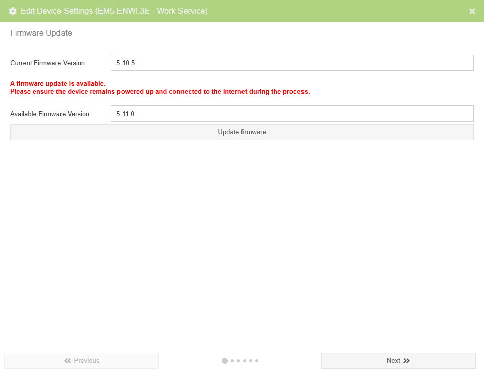
Firmware Update Wizard Page (Common)
The firmware update page will verify the device is running the most recent firmware and, if not, prompt you to update before proceeding with the setup. Firmware updates are occasionally provided to add new features and resolve issues. It is always recommended to use the most recent version of firmware.
Device Specific Wizard Page(s)
Jump to the appropriate section for a description of device specific wizard pages
- Single-Phase Electricity Monitors
- 3-Phase Electricity Monitors
- Inline Power Monitors
- Flow Pulse Monitors
- Temperature Monitors
Single-Phase Electricity Monitors
Single-phase devices are products with two sensors. An example of a single-phase device is the EYEDRO-HOME Wi-Fi/Ethernet Home Energy Monitor product.
Sensor Settings (Single-Phase Electricity Monitors)
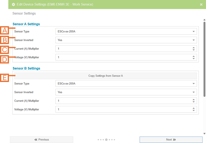
- Sensor Type. Select the sensor that matches your sensor specifications.
- IMPORTANT: This value will impact the readings from the hardware if chosen incorrectly.
- NOTE: If you are unable to find your sensor in the list, ensure the Show Extended Sensor Types option is checked. Not all sensor types are supported on all generations of Eyedro devices.
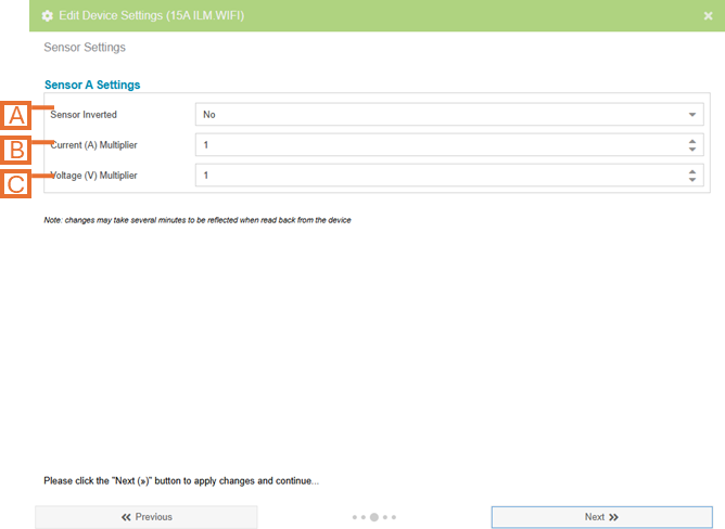
- Sensor Inverted. Flip the polarity of your sensors (i.e. negative readings will become positive readings and vice-versa).
- Current (A) Multiplier (advanced). An additional multiplier to be applied to your current reading (i.e. if the sensor is clamped on a single conductor of a parallel feed).
- Voltage (V) Multiplier (advanced). An additional multiplier to be applied to your voltage reading (i.e. if the sensor is clamped on a single conductor of a balanced 240V circuit).
- Copy settings button. For devices with more than one sensor, a button is provided to copy the settings from the previous sensor to speed up the configuration process.
Advanced Settings (Single-Phase Electricity Monitors)
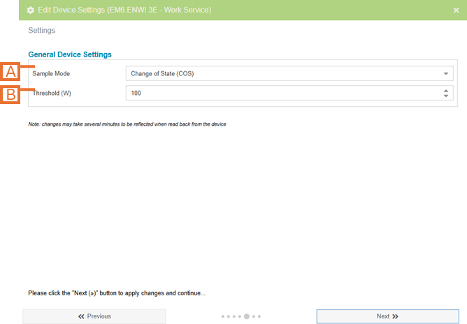
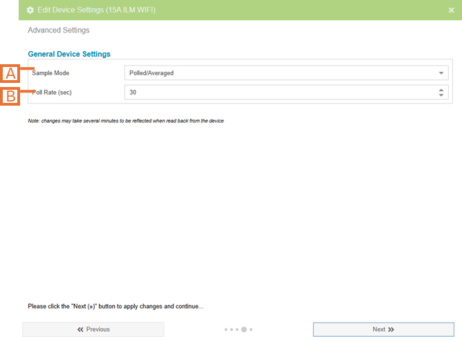
- Sample Mode (advanced). Change the method used to sample data.
- NOTE: The default sample mode is COS and should not be modified unless instructed to. If set incorrectly, this setting can have a significant impact on system bandwidth and responsiveness.
- Change of State (COS) only sends data when it detects a change in value.
- Polled mode sends readings at a fixed interval.
- NOTE: The default sample mode is COS and should not be modified unless instructed to. If set incorrectly, this setting can have a significant impact on system bandwidth and responsiveness.
- Sample Mode Options (advanced). Options are presented based on the Sample Mode selected.
- When Sample Mode is set to Change Of State, this specifies the minimum difference in wattage readings for a new data point to be recorded.
- When Sample Mode is set to Polled, this specifies the period in seconds at which data points will be captured.
- Power Supply (advanced – not shown). Select the power supply connected to the electricity monitor.
- IMPORTANT: This value will impact the readings from the hardware if chosen incorrectly.
Validate Configuration (Single-Phase Electricity Monitors)
The validate configuration page is provided as a means to validate the measurements are as expected.
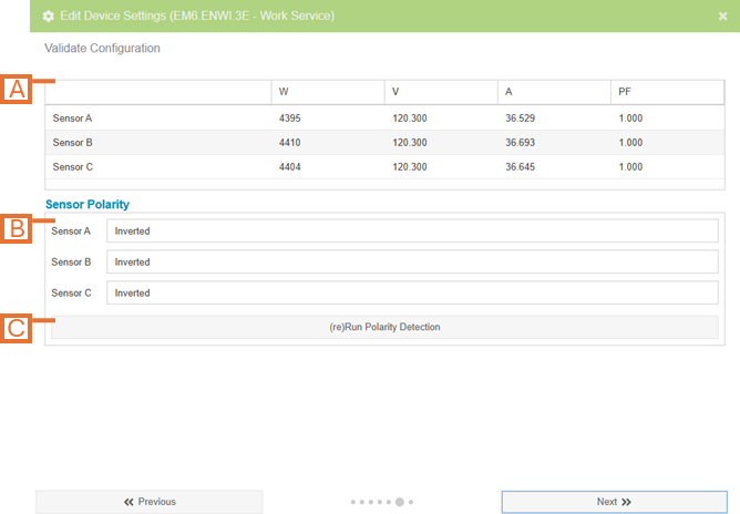
- Device Data panel. The most recent measurements reported by the device (updated every few seconds).
- Sensor Polarity panel. Displays the current Invert settings for each sensor port (Inverted or Not Inverted).
- (Re)Run Polarity Detection button. The sensors used to measure electricity consumption are directional and often they are installed on the circuit(s) “backwards” resulting in positive and negative readings being reported on different sensors. Use this feature to run polarity detection on the device. By clicking this button, the device will toggle the invert settings as required to make all measurements the same polarity (positive).
- NOTE: Not all generations of Eyedro hardware support this feature.
- NOTE: It may take several minutes from the time this button is clicked for the positive measurements to be reflected.
3-Phase Electricity Monitors
3-phase devices are products with three sensors. An example of a three-phase device is the EB6-EW-E3 Wi-Fi/Ethernet Electricity Meter for 3-Phase product
3-Phase Power Settings (3-Phase Electricity Monitors)
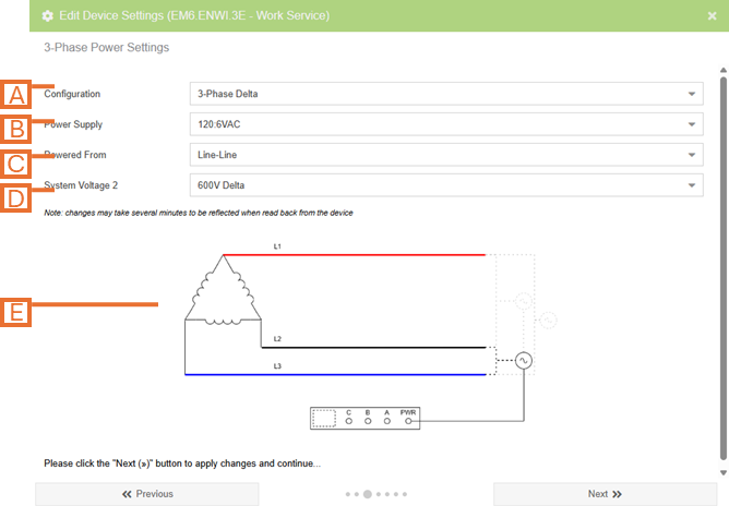
- Configuration. Set the voltage configuration for the panel that you are monitoring. Options are:
- 3-Phase Wye.
- 3-Phase Delta.
- 3-Phase High-Leg Delta.
- 3-Phase Corner Grounded Delta.
- Single Phase.
- Power Supply. Select the power supply connected to the electricity monitor.
- IMPORTANT: This value will impact the readings from the hardware if chosen incorrectly.
- Powered From. Select how the Eyedro device is powered relative to the circuit being monitored. Eyedro monitoring devices require that they be powered from the circuit being monitored.
- NOTE: not all generations of Eyedro hardware support this feature.
- System Voltage. Define the nominal voltage of the system being monitored.
- IMPORTANT: This value will impact the readings from the hardware if chosen incorrectly.
- Topology Diagram. The image shown will reflect the options selected on this page.
Sensor Settings (3-Phase Electricity Monitors)
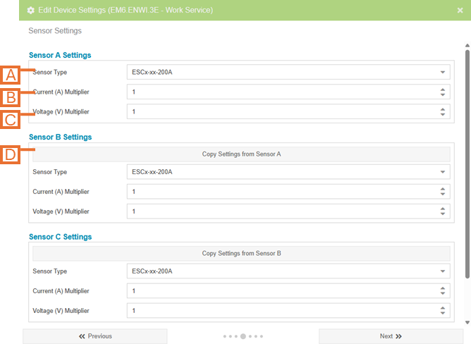
- Sensor Type. Select the sensor that matches your sensor specifications.
- IMPORTANT: This value will impact the readings from the hardware if chosen incorrectly.
- NOTE: If you are unable to find your sensor in the list, ensure the Show Extended Sensor Types option is checked. Not all sensor types are supported on all generations of Eyedro devices.
- Current (A) Multiplier (advanced). An additional multiplier to be applied to your current reading (i.e. if the sensor is clamped on a single conductor of a parallel feed).
- Voltage (V) Multiplier (advanced). An additional multiplier to be applied to your voltage reading.
- NOTE: not all generations of Eyedro hardware support this feature on 3-phase monitoring devices.
- Copy settings button. For devices with more than one sensor, a button is provided to copy the settings from the previous sensor to speed up the configuration process.
Advanced Settings (3-Phase Electricity Monitors)
- Sample Mode (advanced). Change the method used to sample data.
- NOTE: The default sample mode is COS and should not be modified unless instructed to .If set incorrectly, this setting can have a significant impact on system bandwidth and responsiveness.
- Change of State (COS) only sends data when it detects a change in value.
- Polled mode sends readings at a fixed interval.
- NOTE: The default sample mode is COS and should not be modified unless instructed to .If set incorrectly, this setting can have a significant impact on system bandwidth and responsiveness.
- Sample Mode Options (advanced). Options are presented based on the Sample Mode selected.
- When Sample Mode is set to Change Of State, this specifies the minimum difference in wattage readings for a new data point to be recorded.
- When Sample Mode is set to Polled, this specifies the period in seconds at which data points will be captured.
Validate Configuration (3-Phase Electricity Monitors)
The validate configuration page is provided as a means to validate the measurements are as expected.
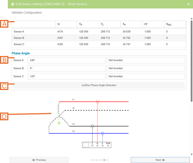
- Device Data panel. The most recent measurements reported by the device (updated every few seconds).
- Phase Angle panel. Displays the results from the last phase angle detection run.
- (Re)Run Phase Angle Detection button. This feature is used to determine the direction of each installed sensor as well as which of the three phases each sensor is connected to.
- NOTE: Not all generations of Eyedro devices support this feature. It may take several minutes from the time this button is clicked for the measurements to be reflected.
- Topology Diagram. The image shown will reflect the device configuration as well as the results of the phase angle detection algorithm.
Inline Power Monitors
Sensor Settings (Inline Power Monitors)
- Sensor Inverted. Flip the polarity of your sensors (i.e. negative readings will become positive readings and vice-versa).
- Current (A) Multiplier (advanced). An additional multiplier to be applied to your current reading.
- Voltage (V) Multiplier (advanced). An additional multiplier to be applied to your voltage reading.
Advanced Settings (Inline Power Monitors)
- Sample Mode (advanced). Change the method used to sample data.
- NOTE: The default sample mode is COS and should not be modified unless instructed to. If set incorrectly, this setting can have a significant impact on system bandwidth and responsiveness.
- Change of State (COS) only sends data when it detects a change in value.
- Polled mode sends readings at a fixed interval.
- NOTE: The default sample mode is COS and should not be modified unless instructed to. If set incorrectly, this setting can have a significant impact on system bandwidth and responsiveness.
- Sample Mode Options (advanced). Options are presented based on the Sample Mode selected.
- When Sample Mode is set to Change Of State, this specifies the minimum difference in wattage readings for a new data point to be recorded.
- When Sample Mode is set to Polled, this specifies the period in seconds at which data points will be captured.
Flow Pulse Monitors
Sensor Settings (Flow Pulse Monitors)
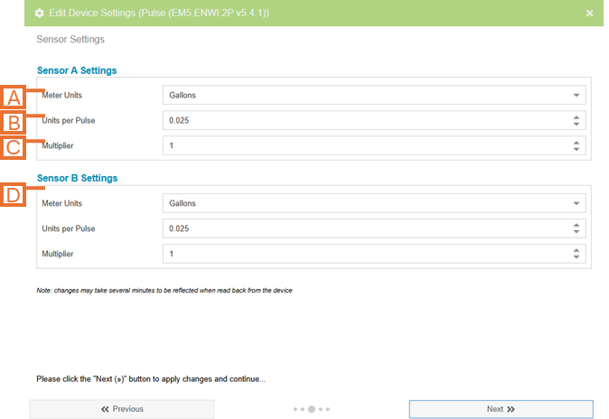
- Meter Units. The units of measure for the meter data.
- NOTE: This should match the meter. Displayed unit preference can be set independently in the Display Groups configuration of MyEyedro.
- Units per Pulse. The number of data units represented by each pulse.
- NOTE: For dry contact pulse outputs, this is often indicated on the outside of the meter. Refer to the meter manufacturers documentation.
- NOTE: For gas/water flow meter installations, this is the computed K-Factor. Refer to the process outlined in the Flow Meter Installation and Product Guide for details.
- Multiplier (advanced). An additional multiplier to be applied to your current reading.
Advanced Settings (Flow Pulse Monitors)
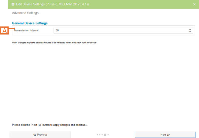
- Transmission Interval (advanced). The period, in seconds, over which the pulses will be counted and a new data point will be captured.
Temperature Monitors
Advanced Settings (Temperature Monitors)

- Transmission Interval. The period, in seconds, over which the temperature measurements will be averaged and a new data point will be captured.
Sensor Calibration (Temperature Monitors)
Sensor calibration is used to trim the temperature measurements to improve accuracy. The calibration functionality is also available at a future time directly from the MyEyedro.
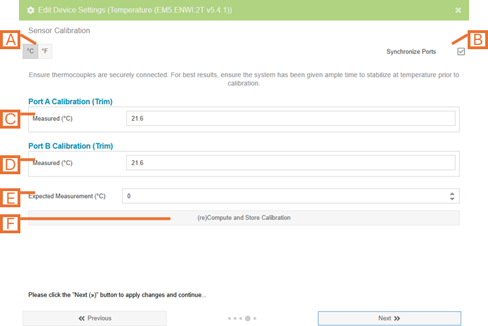
- Choose the desired temperature units.
- If both sensor ports are being calibrated (i.e. using the same ice bath or hot plate), check the Synchronize Ports option.
- Measured value for Port A is displayed. NOTE: value is read only.
- Measured value for Port B is displayed. NOTE: value is read only.
- Using a third party measuring device, enter the expected measurement value.
- Click the Compute and Store Calibration button to compute and store the trim values for ports A and B.
IMPORTANT: Ensure the thermocouples are securely connected to the temperature monitoring device and the device is powered on actively communicating to the internet. The device and connected thermocouples should be given time to stabilize temperature prior to calibration.
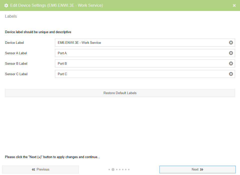
Device Label Wizard Page (Common)
This page is used to update labels for the device and, if applicable, the sensors. You should always provide unique and descriptive labels (i.e. Service Entrance, Boiler 1, etc.) especially if you have multiple devices added to your account.
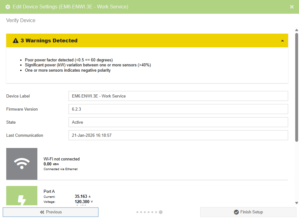
Verify Wizard Page (Common)
The verify page will perform various checks on the configuration and real-time measurement data and provide a list of warnings and/or errors detected.
NOTE: This wizard page will only exist if the Show Verify Panel options is unchecked. Otherwise, the verify panel will always be visible on the right side of the plugin.